|
IO(0)
IO(1)
IO(2)
IO(3)
IO(4)
IO(5)
IO(6)
IO(7)
IO(8)
IO(9)
IO(10)
IO(11)
IO(12)
IO(13)
IO(14)
IO(15) |
P0(9)
P0(8)
P0(30)
P0(21)
P0(20)
P0(29)
P0(4)
P0(5)
P0(6)
P0(7)
P0(13)
P0(19)
P0(18)
P0(17)
P0(16)
P0(15) |
RXD(1)
TXD(1)
EINT0
EINT2 |
PWM1
PWM2
PWM3
PWM4
PWM5
PWM6
PWM7
PWM8
|
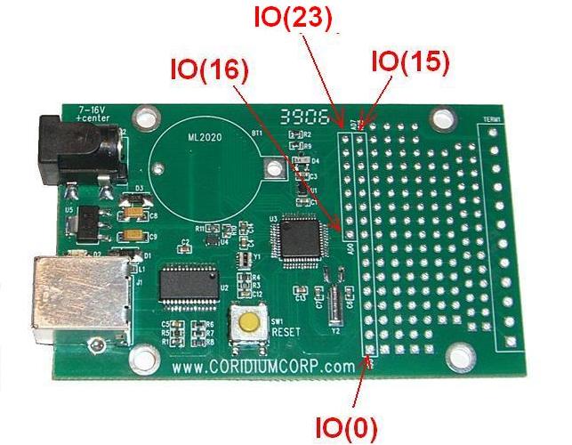
Input/Outputs -- user controlled
0-3.3V level
4mA
drive when configured as Outputs
5V tolerant
- use limiting resistor when connecting to a 5V
supply
IO(15) connected to LED |
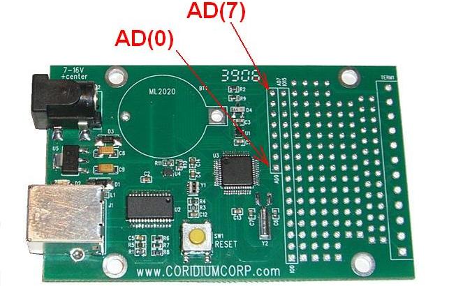
AD(0)
AD(1)
AD(2)
AD(3)
AD(4)
AD(5)
AD(6)
AD(7) |
P0(22)
P0(23)
P0(24)
P0(10)
P0(11)
P0(12)
P0(25)
P0(26) |
IO(16)
IO(17)
IO(18)
IO(19)
IO(20)
IO(21)
IO(22)
IO(23) |
|
10 bit A/D inputs
may also be used as digital
Input/Outputs IO(16-23)
-- user controlled
when used as analog lines,
voltage levels should not exceed 3.3V
|
Dual Use AD pins
On reset or power up the AD pins are configured as AD
inputs. To change those to digital IOs, the user must individually specify
a control direction using INPUT(x), OUTPUT(x), DIR(x), or
IO(x) commands. After that they will remain digital IOs until the
next reset or power up.
PWM pins
All pins can be used for the software PWM function, and 8 pins
can be used for the hardware driven HWPWM function.
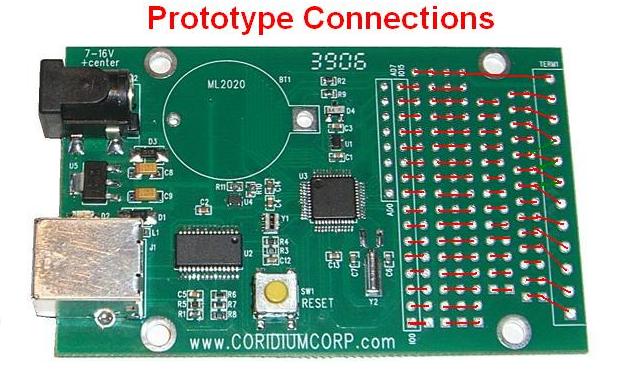
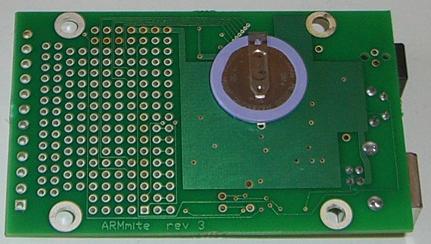
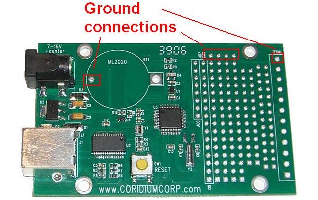
Battery Real Time Clock
The ARMmite board is designed to accept a Panasonic ML2020/H1C
rechargeable Lithium battery at position BT1. This battery powers the real time
clock of the LPC2103. The contents of RAM is not kept alive while running
on battery, and the CPU restarts the user program in Flash when power is
restored. This battery is designed to maintain power for a few days
without power, and will recharge fully in about 1 day.
Power connection
Power when not being supplied by a USB connection uses a 2.1mm
barrel connector (Cui PJ-002A). Diodes allow both USB and separate
power to be connected simultaneously. If you
are using an unregulated wall transformer, you must check the open circuit
voltage and it MUST be less than 12V.
Pin spacing
The spacing in the prototype area is 0.1" and the terminal strip
row on the right side is designed for 3.5mm terminal strips.
REV 3
When USB power is not used, a 5-12V supply is required. If
5V is required for some portion of your circuit, it is suggested that a
regulated 5V supply be used for input power. These are available from
SparkFun.
A push button switch and pull-up resistor can also be mounted
(connected to IO(2)). The optional battery for the real time clock (Panasonic
ML2020) can be mounted on the back of the PCB. The VL2020/HFN will also
work, though it is more expensive and has less power.
_____________________________________________________________________________________________________
REV 2
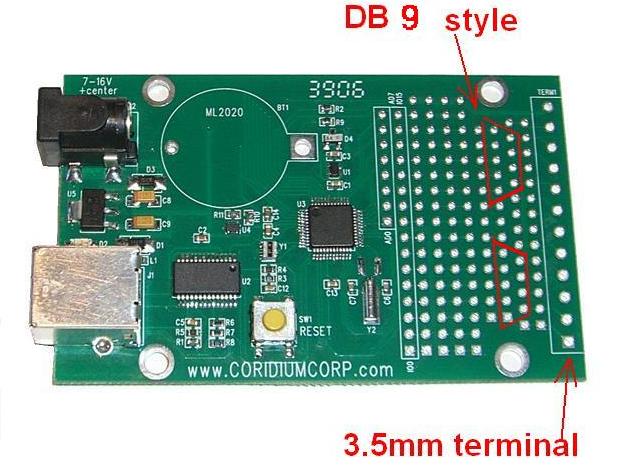
suggested terminal strip On Shore Tech ED550/12DS or equivalent
3.5mm pitch connector (available at Digikey)