The SuperPRO is footprint and pin compatible with the Arduino PRO. In
addition it has an onboard 5V regulator so it is compatible with 5V shield
boards. The SuperPRO also has an RTC crystal and provision for a battery.
The PROplus has only a 3.3V power supply and does not include the RTC
crystal. Both boards can be used with 5V TTL signals.
BASIC or C programs can be downloaded using the installed test connector
using the USB dongle contained in Coridium's evaluation kit or using the SparkFun USB Basic Breakout board or FTDI cable from Digikey. More details on these
connections here.
Digital IO connections -- rev 5
or later
The rev 5 adds a parallel connection for pins
that are on 0.1" centers. This artwork is also shared with the
PROplus version of the board.
The SuperPRO uses an LPC1756 and has 5V and 3.3V
supplies.
The simpler PROplus uses an LPC1751 and has only
the 3.3V supply.
Port pins can be controlled with the
P0..P4 keywords . and with firmware 8.12 or
later the original
IO, IN, OUT.. keywords
. More details on the GPIOs can be found in the NXP User Manual.
Below is a diagram of the pins, note it has been
rotated 90 degrees to make it easier to read,
All boards rev 5 and later share the SAME
pinouts, except for the location of the load-C jumper. To use IO(x) with x
greater than 32, firmware 8.11 or later has to be used. IO(32) is the
equivalent of P1(0) and can be accessed either way in the latest firmware, in
earlier versions P1(0) was the way to access that pin.
Special purpose pins
RESET pin starts the ARM program if the
BOOT(P2.10) pin is high. If you use P2.10 as an input you MUST make sure
it is in the high state when RESET is asserted, otherwise your program will NOT
start.
The LPC1756 supports a number of dedicated functions.
Those include 4 UARTs, USB, 2 SSPs, 1 SPI, 2 CAN, 2 I2C, I2S, 2
multi-channel PWMs, Quadrature Encoder, dedicated motor control PWM, interrupts,
timer counter capture and match.
In addition most can be configured with pull-ups and default to
pull-ups following reset.
Details can be found in NXP's User manual.
UARTs are enabled by calling BAUD(x) for x=0 to 3. UART0
is enabled by default as the programming debug connection. The pin
assignment BASIC uses is in the following table (you can change the settings by
changing the PINSEL registers, details in the NXP User Manual)
| UART |
BASIC |
NXP |
UART |
| RXD(0) |
IO(3) |
P0(3) / AD(6) |
UART0 |
| TXD(0) |
IO(2) |
P0(2) / AD(7) |
|
| RXD(1) |
IO(65) |
P2(1) |
UART1 |
| TXD(1) |
IO(64) |
P2(0) |
|
| RXD(2) |
IO(73) |
P2(9) |
UART2 |
| TXD(2) |
IO(72) |
P2(8) |
|
| RXD(3) |
IO(157) |
P4(29) |
UART3 |
| TXD(3) |
IO(156) |
P4(28) |
|
Analog connections
4 A/D converters are readily available, Analog
2-4. 2 more are available, but share the pins with UART0 -- what was NXP
thinking, I have no idea.
1 10 bit DAC is available shared with AD(3)
available on the SuperPRO (not on PROplus)
On reset or power up the AD pins are configured
by software as AD inputs. To change those to digital IOs, the user
must write to the appropriate PINSEL register, or with version 8.11 firmware or
later you can change it to an IO by accessing the corresponding IO pin in the
following table.
| AD |
BASIC |
NXP |
| AD(2) |
IO(25) |
P0(25),DACOUT |
| AD(3) |
IO(26) |
P0(26) |
| AD(4) |
IO(62) |
P1(30) |
| AD(5) |
IO(63) |
P1(31) |
| AD(6) |
IO(3) |
RXD(0)/P0(3) / AD(6) |
| AD(7) |
IO(2) |
TXD(0)/P0(2) / AD(7) |
The LPC1756 does support an external
reference for the A/D converters, but to use the Arduino AREF pin a jumper
is required (details on the schematic)
The A/D input requires a drive impedance of 7.5K
or less (see NXP LPC175x spec sheet). We've also found a 100 to 1000 pF
cap from AD input to GND can remove high frequency noise affecting high order
bits in the converter.
Analog Isolation
The rev 6 and 7 boards isolate both GND and power
for the analog section using ferrite beads.
to add isolation to rev 4/5 boards
-
The LPC17xx series chips AD converter are
sensitive to high frequency noise on the analog GND (Vssa) or on the AD inputs
themselves. A symptom that will show up is bits in any bit position turned
on/off when the conversion is done. This makes it hard to average out, but
conversion can be voted on, choosing 2/3 conversions that agree within a few
bits. The occurrence of these errors is in less than 1% of the conversions,
unless your setup is very noisy.
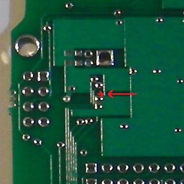
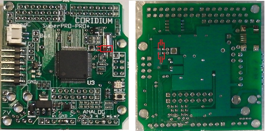
Another option is to change the analog GND
connection on the board. Do this by cutting the trace on the back side
between GND under the crystal and the GND connected to Vssa (shown on the
picture below)
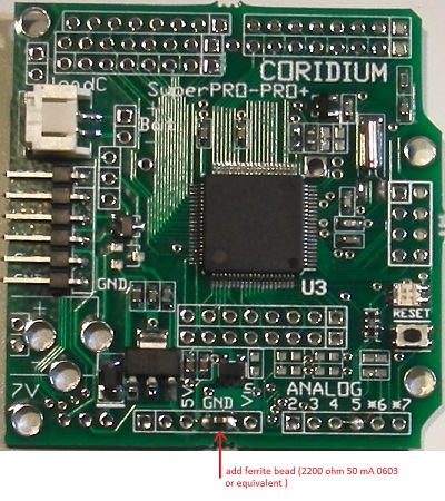
Then connect digital GND to analog GND using a
ferrite bead, a convenient place to do this is on the front side as shown
below.
Pin limitations
P0.29 and P0.30 direction control must be done in
parallel, they can be both outputs or both inputs, but not mixed. With
firmware 8.11 or later, changing the direction of either P0.29 or P0.30 will
change the other pin.
Power connections --
SuperPRO
Pads for a Cui PJ-002A or
SparkFun
PRT-119 power connector are available in the lower left hand
corner.
For both battery and 6V input, 2 pin 0.1" spaced
holes are available for wires or headers. When using the battery
connector, total current draw for the board must be limited to 200mA. If
you want to use more current, you should install a jumper around the D2 diode
(holes are available above D2).
Diode steering allows power to be supplied from a barrel
connector from a 6V unregulated source, 5V USB test connector, or the battery
connector. Because of the Schottky diodes, all 3 power sources can be
connected simultaneously. If you are using an
unregulated wall transformer, you must check the open circuit voltage and it
MUST be less than 12V.
When the 6V source is used, 5V Arduino shields can be powered
from the SuperPRO.
The schematic below describes this circuit on the SuperPRO
Power connections --
PROplus
Pads for a Cui PJ-002A or
SparkFun
PRT-119 power connector are available in the lower left hand
corner.
For both battery and 6V input, 2 pin 0.1" spaced
holes are available for wires or headers. When using the battery
connector, total current draw for the board must be limited to 200mA. If
you want to use more current, you should install a jumper around the D2 diode
(holes are available above D2).
Diode steering allows power to be supplied from a barrel
connector from a 6V unregulated source, 5V USB test connector, 5V from a shield
or the battery connector. Because of the Schottky diodes, all 3 power
sources can be connected simultaneously. If you are
using an unregulated wall transformer, you must check the open circuit voltage
and it MUST be less than 12V.
The PROplus only has the 3.3V regulator, so it cannot supply
power to a 5V shields.
The schematic below describes this circuit on the PROplus
Power connections details
The 3.3V regulator can supply 50 mA, with most
being used by the LPC2103. The 3.3V connection next to RESn on the lower
power connector is only connected if the shorting pads are shorted (NOT the
factory default).
The analog GND should be used to connect to the
GND of analog inputs. Digital and Analog GNDs are connected together with
a small trace, but to minimize noise you should use the analog GND only for
analog signals.
Jumpers and test connector for Program
Download
The USB Dongle from Coridium will supply 5V from the USB to
power the ARMmite PRO. It also controls the RESET and BOOT(P2.10) signals to
automatically load C or BASIC programs using MakeItC or BASICtools.
Remember, if you load a C program, it will erase the BASIC firmware and you will
not be able to load BASIC programs after that.
When using the SparkFun FTDI Basic Breakout Board, a limited
amount of power can be supplied from the BBB, but this is limited to 50 mA and
after diode drops, its about 2.8V to the LPC2103. In practice this will
run, but it is outside the part specifications, so it should be
limited in use.
Also with the SparkFun FTDI Basic Breakout Board to load a
C program, the LOAD C jumper needs to be installed, then removed to run the
program. BASIC programs can be loaded and controlled using the SparkFun
board, with no additional steps/jumpers.
PROplus
SuperPRO
An alternative is to use a 2 pin header with a shorting block
(pictured below)
Real Time Clock Oscillator
The RTC oscillator of the LPC17xx
parts has been resolved. The first generation
parts which were shipped in early 2011 had an unreliable oscillator and this has
been corrected by NXP.
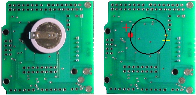
A 32 KHz crystal and diode for battery backup with an optional
ML2020 rechargeable Li battery.
A Panasonic ML2020H rechargeable battery may be added to keep
the real time clock running when power is removed. The battery is mounted
on the back of the board as shown below. The VL2020/HFN will also work,
though it is more expensive and has less power.
USB connector option for power and SPI Flash
option
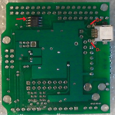
The rev 6/7 boards add pads for an optional
SPI Serial Flash (note pin 1 location). Also pads for a USB mini-B
connector have been added, this is intended primarily to supply power, and the
data lines are connected to pads. These options can be installed at
Coridium for orders of 10 boards or more. Contact
sales@coridium.us for
details.
Main Clock Crystal
option
You can add a
12 MHz crystal with 39pf 0603 load caps, for use as a more
accurate clock source. Locations marked below